Installing the Head Assembly
Caution: To prevent the kiosk from toppling over, make sure to hold the bucket down.
1.Carefully position the head assembly on the tray.
Note: Observe proper alignment because there are hooks and PEM nuts on both sides of the tray. P–shaped slots are provided in the head assembly as clearances for the hooks and PEM nuts. Use both the left and the right screws as guides for the alignment of the P–shaped slots and the PEM nuts.
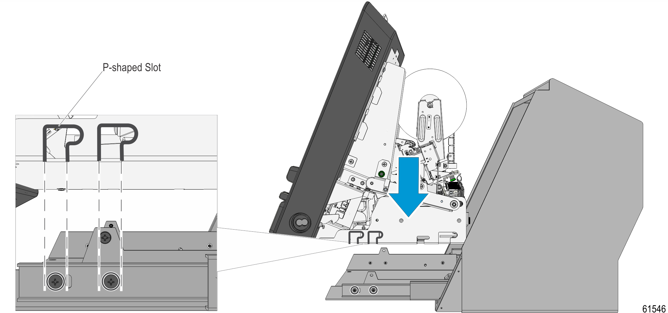
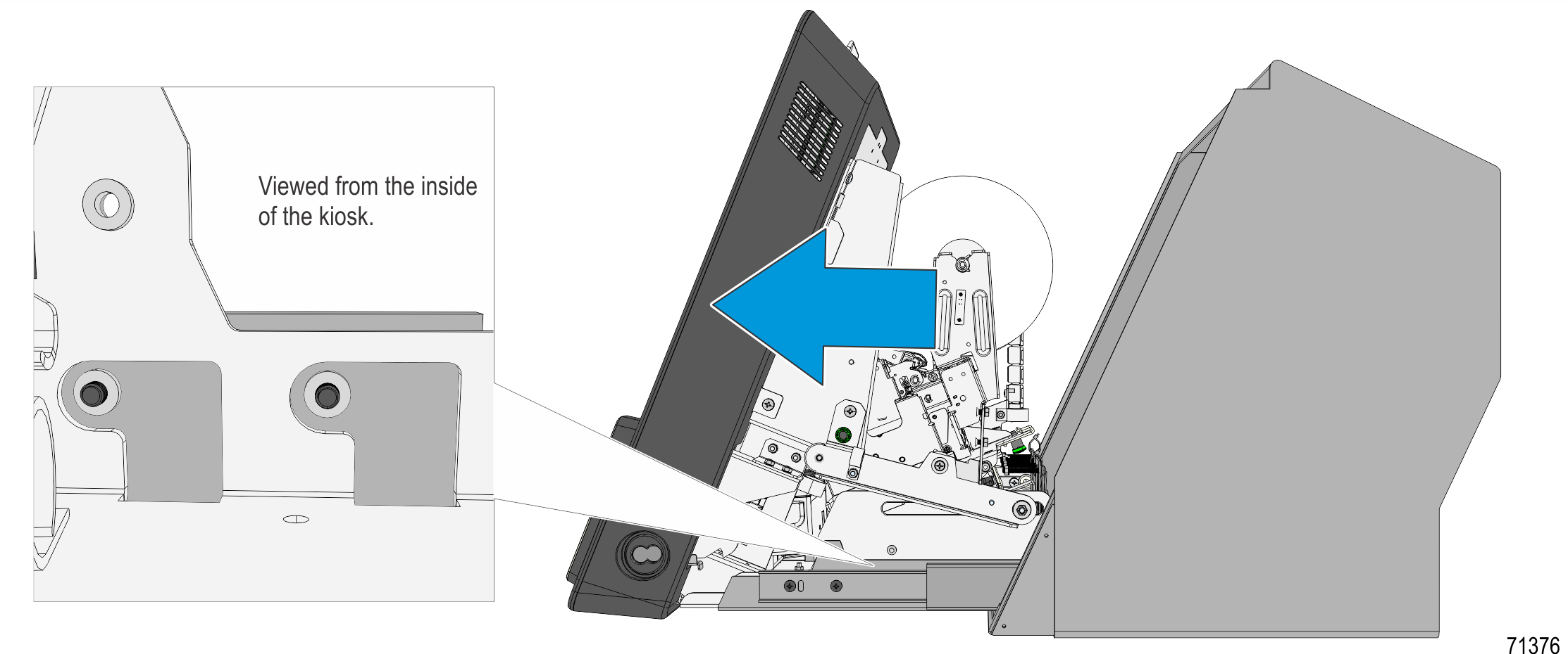
2.With the P–shaped slots and screws properly aligned, carefully pull the head assembly toward the front until the screws are on the curved part of the P–shaped slots.
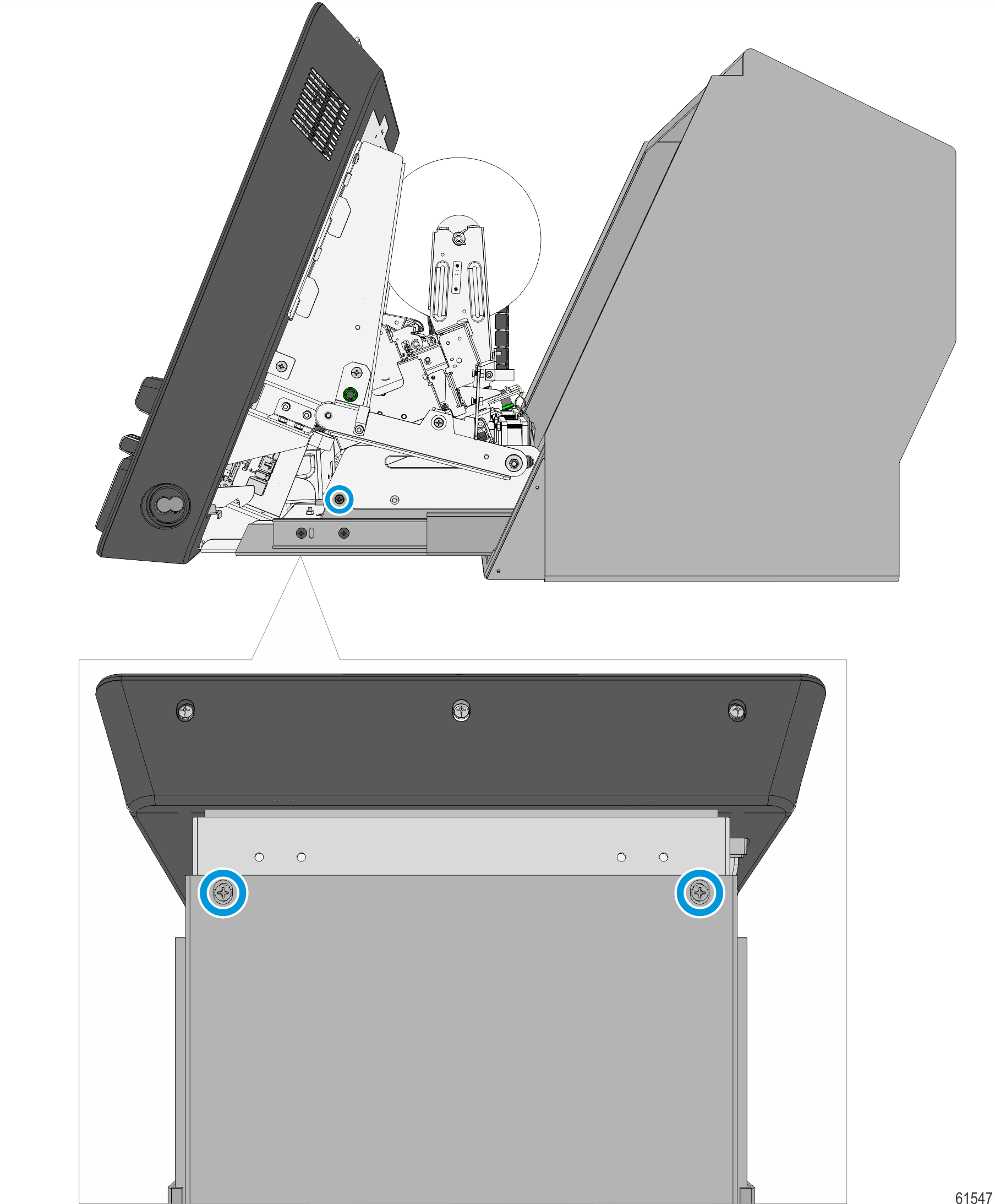
3.Install the two screws, one on each side of the unit, and the two screws at the bottom of the Countertop.
Note: Ensure that the screws are correctly positioned on the slots.
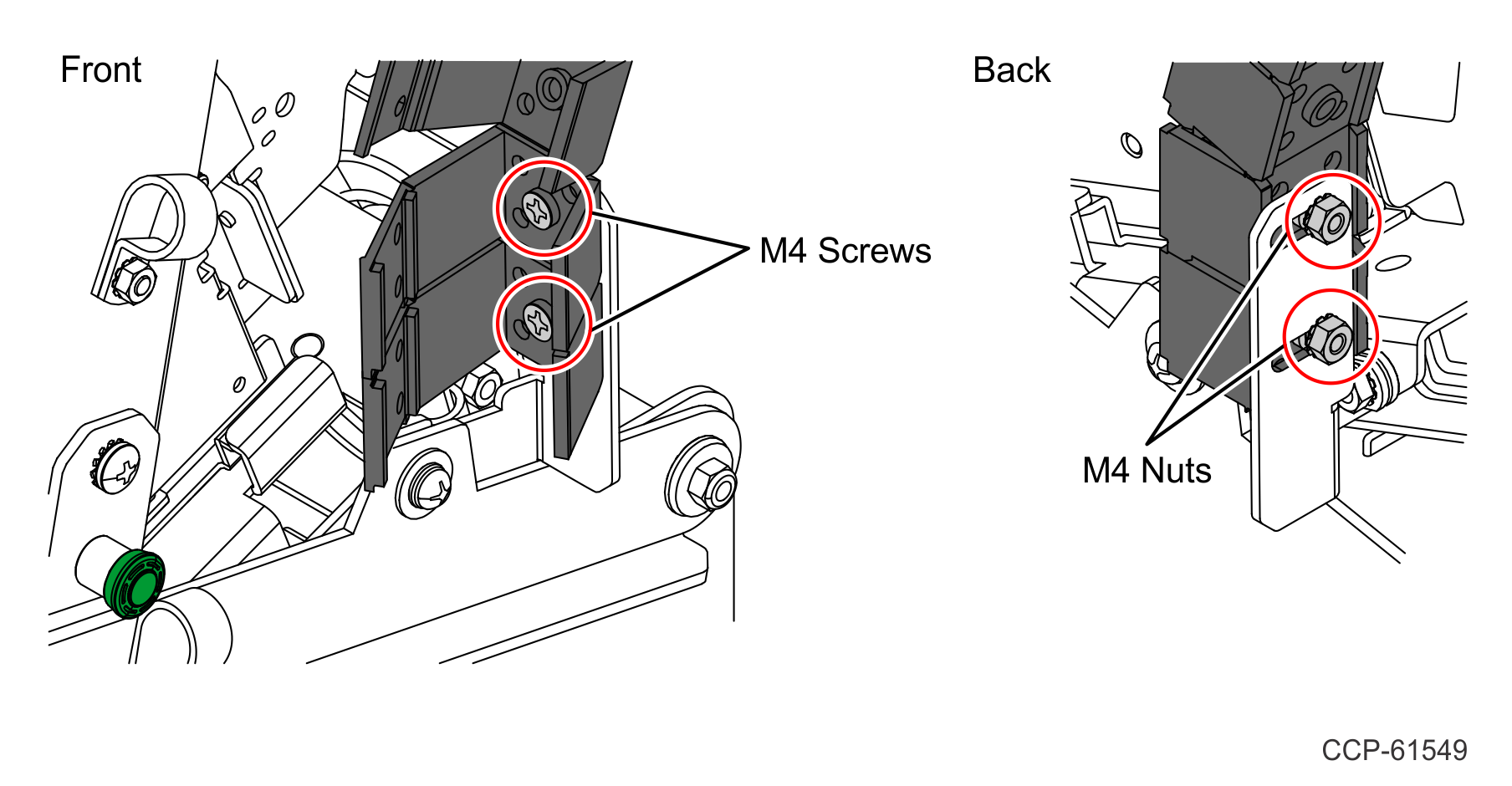
4.Secure the unattached side of the 20–Link Energy Chain to the Chassis Chain Bracket using two M4 Flat Head screws and two M4 Hex nuts.
Note: The fastening torque value is maximum of 3 in-lbs.
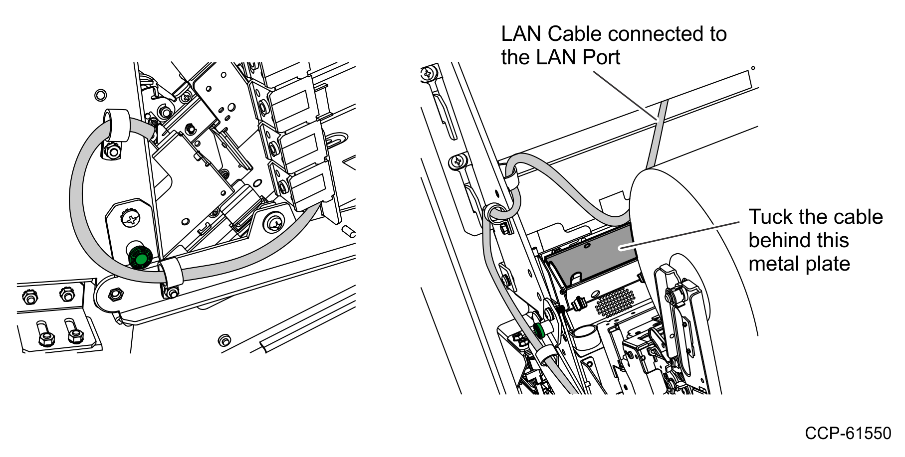
5.Route the LAN Cable from the 20–Link Chain as shown below, and then connect to the LAN Port of the Motherboard. Use two half–inch cable clamps before passing through the chain.
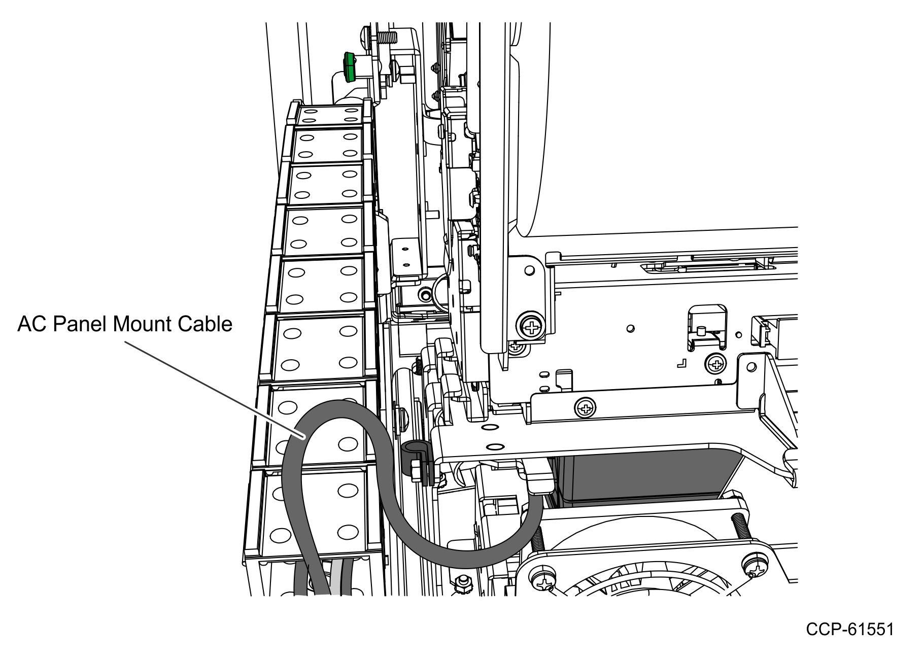
6.Connect the AC Panel Mount Cable to the Power Brick.
a.Route the AC Panel Mount Cable.
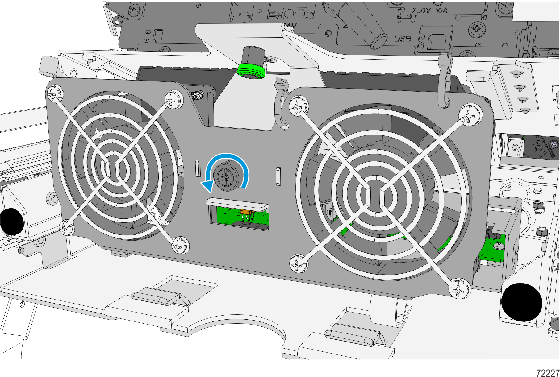
b.Disconnect the Dual Fan Cable.
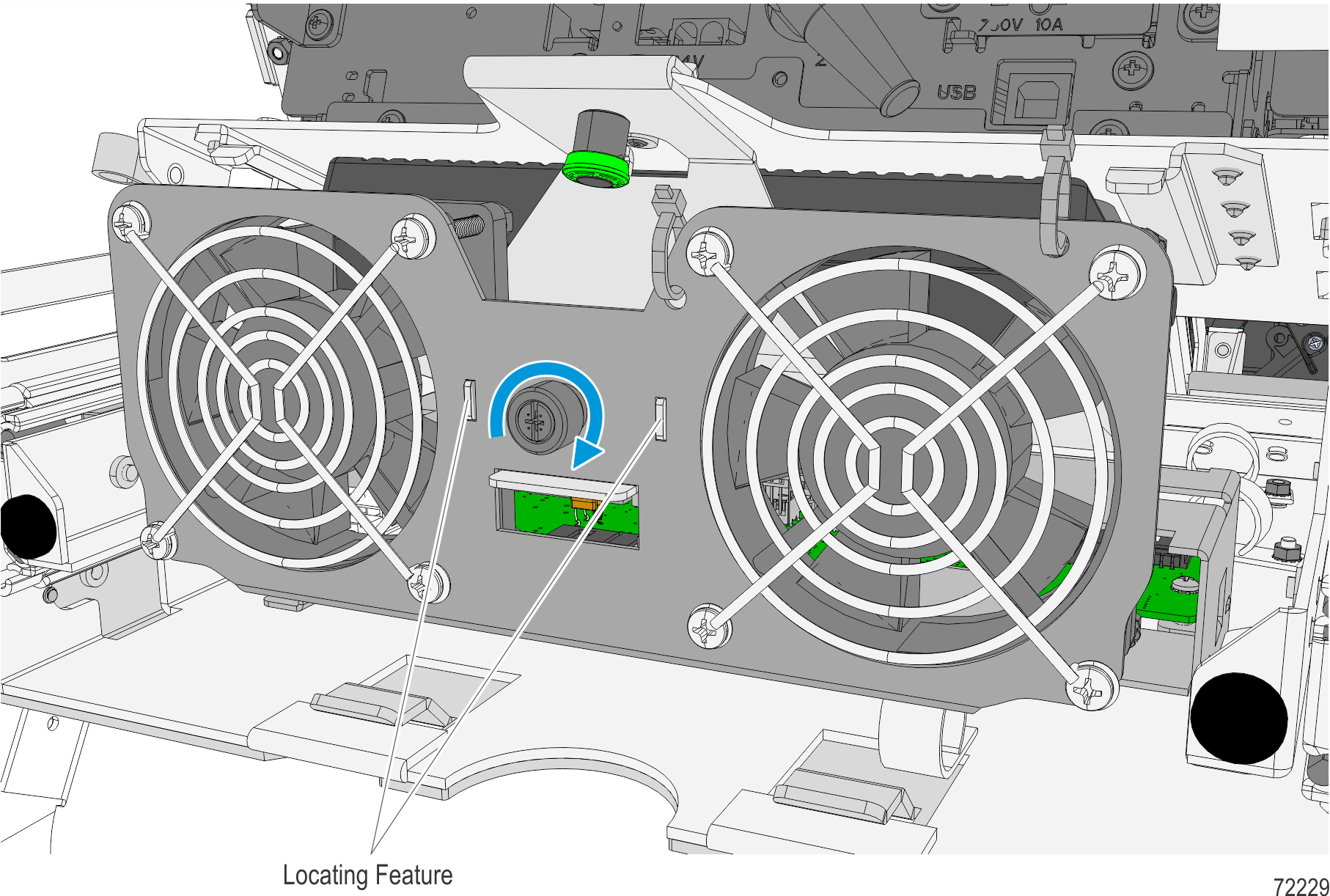
c.Loosen thumbscrew to remove the Dual Fan assembly from the Power Brick Mount Bracket.
d.Pull down the green plunger, and then remove the Power Supply Bracket by sliding it out.
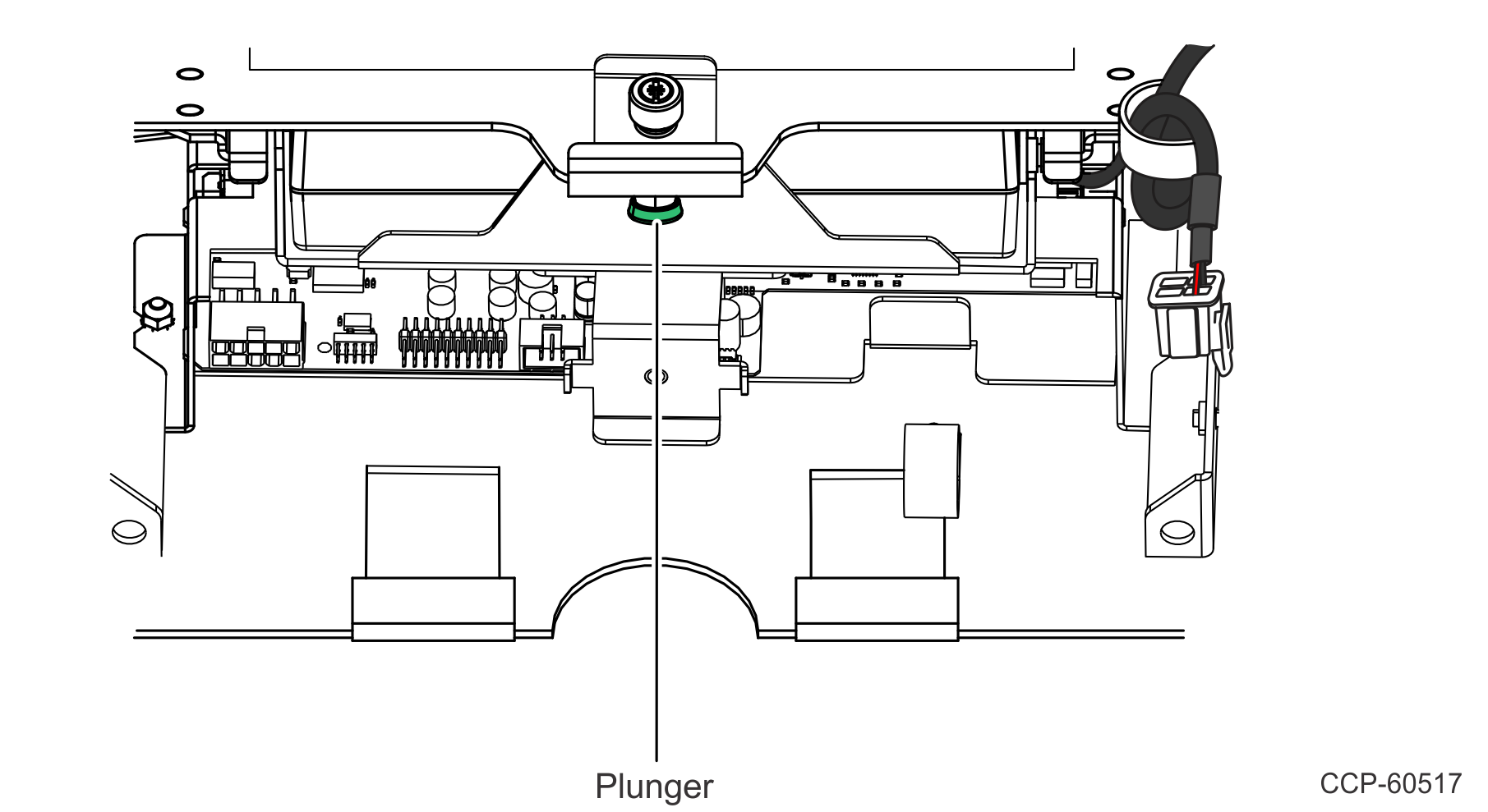
e.Connect the cable to the Power Supply.
Note: Make sure that the connector is fully inserted.
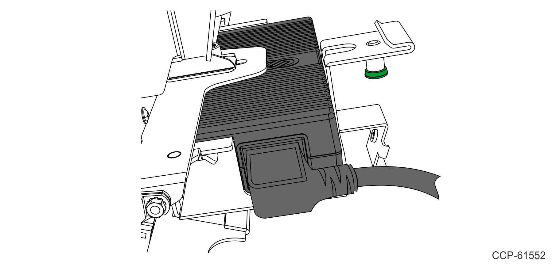
f.Slide in the Power Supply Bracket and secure with plunger.
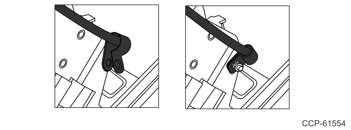
7.Secure the AC Panel Mount Cable to the Printer Bracket.
a.Remove the M4 Hex Nut from the P–loop.
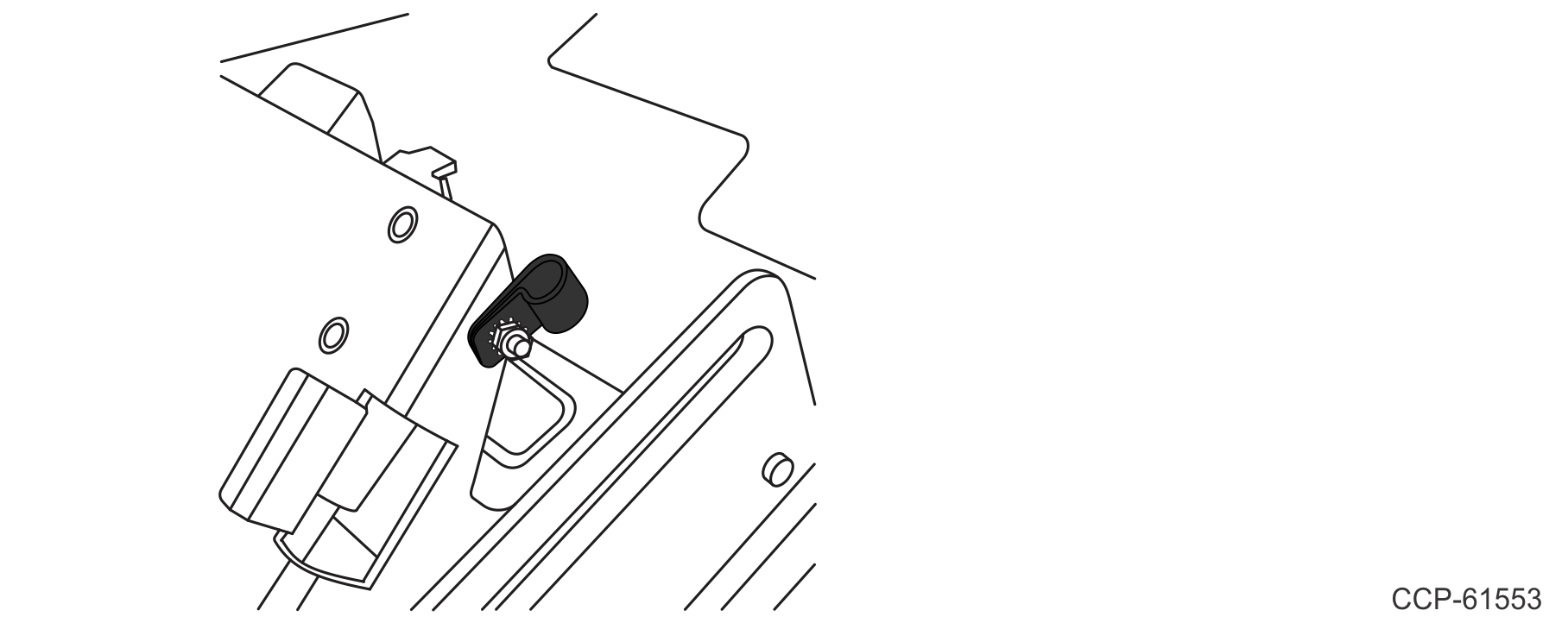
b.Insert the AC Panel Mount Cable to the P–loop and re–install the P–loop.
8.Install the Dual Fan assembly on the Power Brick Mount Bracket using the locating feature. Tighten the thumbscrew to secure the assembly.
9.Connect the Fan Cable to the Fan Power Connector of the I/O Cable.